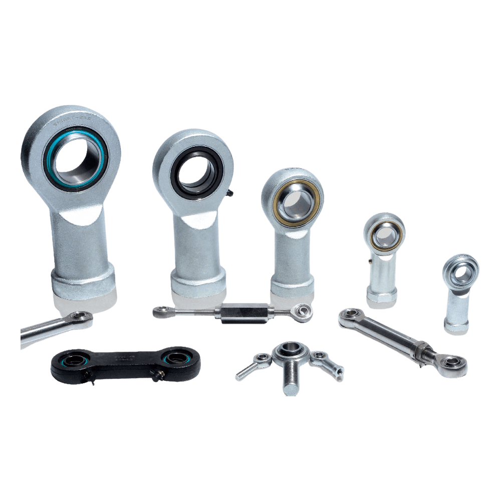
C&H manufactures maintenance-free rod ends with three different sliding contact surface combinations in different series:
• Steel/PTFE composite
• Steel/PTFE fabric
• Steel/PTFE Plastic
Rod ends with either a steel/PTFE composite or steel/PTFE fabric sliding contact surface combination contain a bearing from the standard assortment. The outer ring is staked in place in the housing.
Rod ends with a steel/PTFE plastic sliding contact surface combination consist of a rod end housing and a spherical plain bearing inner ring. Between the housing and the inner ring, a sliding layer of fibre reinforced polymer, containing PTFE, is molded to the housing.
C&H supplies maintenance-free rod ends with a threaded shank with a right-hand thread as standard. All rod ends are also available with a left-hand thread. They are identified by the designation prefix or suffix L .
C&H manufactures maintenance-free rod ends with three different sliding contact surface combinations in different series:
• Steel/PTFE composite:
– GIKR(L) .. PW series
– GAKR(L).. PW series
– GIKR(L) .. PS series
– GAKR(L).. PS series
– SI(L) .. C series / GIR(L)..UK series
– SA(L) .. C series / GAR(L)..UK series
• Steel/PTFE fabric:
– SI(L) .. TXE-2RS series / GIR(L)..UK-2RS series
– SI(L)A .. TXE-2RS series
– SA(L) .. TXE-2RS series / GAR(L)..UK-2RS series
– SA(L)A .. TXE-2RS series
• Steel/PTFE Plastic :
– SI(L)KB .. F series
– SA(L)KB .. F series
The dimensions of C&H maintenance-free rod ends are in accordance with ISO 12240-4:1998.
Male and female threads of C&H rod ends are in accordance with ISO 965-1:1998.
Female rod ends having a fine pitch thread is in accordance with ISO 8139:2009.
Series GIKPR..-PW and GIKPSR..-PS has a fine pitch thread connector for standard pneumatic cylinders to DIN ISO 15552 (right hand thread only).
Tolerance
C&H rod end inner ring dimensional tolerances are in accordance with ISO 12240-1:1998. The tolerances are listed in table 1.
The symbols used in table 1 are explained in the following:
d nominal bore diameter
Δdmp deviation of the mean bore diameter from the nominal
ΔBs deviation of the single inner ring width from the nominal
Inner ring dimensional tolerances for maintenance-free rod ends
Clearance
Radial internal clearance, preload Depending on their design, maintenance-free rod ends may have a radial internal clearance or a light preload. Table 2 lists maximum values for the radial internal clearance as well as for the frictional moment in the circumferential direction caused by preload.
Radial internal clearance and frictional moment for maintenance-free rod ends

